Pneumatic rotary cylinders, also widely known as pneumatic rotary actuators, are specialized pneumatic components designed to convert the energy of compressed air into controlled rotational mechanical motion. Unlike standard linear pneumatic cylinders that produce back-and-forth straight-line movement, these actuators leverage internal mechanical structures to transform the linear force of compressed air into precise, repeatable rotational motion—making them indispensable in automated systems where angular positioning or rotation is required.
At its core, a pneumatic rotary cylinder is a type of pneumatic actuator engineered explicitly for rotational load actuation, rather than linear motion. It serves as a critical motion control component in industrial automation, bridging the gap between compressed air supply and mechanical rotation.
A typical pneumatic rotary cylinder features a compact, integrated design with the following key parts—each contributing to its functionality and durability:
Cylinder Body: The outer housing that contains internal components and maintains air pressure. Constructed from high-strength materials (e.g., aluminum alloy) for lightweight yet robust performance.
Rotary Shaft: The central component that transmits rotational motion to the external load (e.g., grippers, valves). Precision-machined to ensure low friction and accurate positioning.
Piston: A movable internal component driven by compressed air. Its linear movement is the starting point for converting energy into rotation.
Seals: High-performance elastomeric or polymeric seals (e.g., O-rings, piston seals) that prevent air leakage, ensuring efficient pressure retention and long service life.
Air Inlet/Outlet Ports: Two or more ports that control the flow of compressed air into and out of the cylinder, regulating the direction of rotation (clockwise/counterclockwise).
Bearings: Mounted around the rotary shaft to reduce friction during rotation, enhancing smoothness and extending component life.
Fixed Mounting Brackets: Hardware that secures the cylinder to machinery or frames, ensuring stability during operation.
The core purpose of a pneumatic rotary cylinder is to deliver adjustable, reciprocating rotation at specific angles (e.g., 90°, 180°, or custom ranges) for automated tasks. This capability makes it a staple in industries where precision, speed, and reliability are critical—such as material handling, assembly line automation, and process control.
Pneumatic rotary cylinders stand out from standard linear cylinders and other rotary actuation technologies (e.g., electric motors, hydraulic actuators) due to their unique combination of features. These attributes directly address the demands of modern industrial automation:
| Feature | Description | Industrial Benefit |
|---|
| Adjustable Rotation Angle | The rotational range can be fine-tuned (e.g., 0°–190° for adjustable models) or fixed (e.g., 90°, 180°, 270° for standard models) via built-in limiters or external controls. | Adapts to diverse application needs (e.g., 90° valve opening, 180° workpiece flipping) without requiring custom modifications. |
| Built-in Magnetic Ring | A permanent magnetic ring is embedded in the piston or rotary shaft. This enables compatibility with magnetic proximity sensors (e.g., reed switches, Hall-effect sensors) to detect the cylinder’s position and rotation angle. | Enables real-time position feedback for closed-loop control, reducing errors in automated processes (e.g., confirming a gripper has rotated to the correct angle). |
| Efficient, User-Friendly Design | Optimized for easy installation (e.g., standardized mounting holes) and minimal maintenance. The compact layout reduces space requirements, even in dense machinery setups. | Lowers setup time and operational downtime; fits in space-constrained environments (e.g., small robotic cells). |
| Aluminum Alloy Construction | Most cylinders use high-grade aluminum alloy for the body and structural components. This material offers excellent corrosion resistance, temperature tolerance, and moisture/water ingress protection. | Ensures durability in harsh industrial environments (e.g., food processing plants with washdowns, outdoor equipment exposed to humidity). |
| High Output Torque | Leveraging rack-and-pinion or vane-based internal mechanisms, combined with sturdy materials, these cylinders deliver substantial torque relative to their size—even for light-to-medium loads. | Handles tasks like clamping, lifting, or rotating heavy workpieces (e.g., metal components in machining) without compromising speed. |
| Accessory Compatibility | Fully integrable with external components, including mounting brackets, angle limiters, pressure regulators, and sensors. | Customizable to meet specific application requirements (e.g., adding a pressure relief valve for overload protection, or a sensor for position verification). |
The functionality of pneumatic rotary cylinders is tailored to solve common motion control challenges in automation. Their core functions include:
The primary function is to generate adjustable, reciprocating rotation—with angle ranges determined by the cylinder type:
Single-acting models: Typically offer a fixed rotation angle (e.g., 90°), using compressed air for one direction of rotation and a spring for return.
Double-acting models: Provide adjustable rotation (e.g., 0°–180° or 0°–190°), with compressed air driving rotation in both clockwise and counterclockwise directions.
Equipped with precision-machined components (e.g., rack-and-pinion gears, high-tolerance bearings) and compatible with position sensors, these cylinders achieve angular positioning accuracy of ±0.5° to ±1° (depending on the model). This ensures consistent performance in tasks like:
Robotic arm joint rotation
Fixture alignment for machining
Valve actuation in process control (e.g., regulating fluid flow in pipelines)
Compared to electric servo motors (which require complex controllers) or hydraulic actuators (which need fluid reservoirs and pumps), pneumatic rotary cylinders offer:
Lower upfront and maintenance costs
Simpler integration with existing pneumatic systems
Faster response times (critical for high-speed automation)
They are ideal for applications where high torque or continuous rotation is not required—such as pick-and-place handlers, packaging machinery, or small-scale assembly tasks.
Thanks to corrosion-resistant materials (aluminum alloy) and sealed internal components, pneumatic rotary cylinders maintain stable performance in:
Temperature ranges of 0°C–60°C (with antifreeze modifications for sub-zero environments)
Humid or dusty conditions (e.g., warehouses, construction sites)
Washdown environments (e.g., pharmaceutical or food processing plants)
The operation of a pneumatic rotary cylinder relies on a simple yet effective energy conversion process: converting the linear force of compressed air into rotational motion via internal mechanical mechanisms. The two most common designs are rack-and-pinion and vane-type—with rack-and-pinion being the most widely used in industrial applications.
Air Inlet: Compressed air (filtered to remove contaminants) is supplied to one of the cylinder’s inlet ports. This air pressure acts on the piston, pushing it linearly along the cylinder body.
Linear-to-Rotary Conversion: The piston is connected to a rack (a straight gear with teeth). As the piston moves, the rack engages with a pinion gear (a small circular gear) attached to the rotary shaft. The linear motion of the rack causes the pinion gear—and thus the rotary shaft—to rotate.
Direction Control: To reverse rotation, compressed air is redirected to the opposite inlet port. This pushes the piston back in the reverse direction, rotating the rack, pinion, and shaft counterclockwise (or clockwise, depending on the initial direction).
Position Sensing (Optional): If a magnetic ring is installed, a external sensor detects the piston’s position as it moves. This feedback is sent to a controller, which adjusts air flow to stop rotation at the desired angle.
Sealing & Efficiency: Seals around the piston and ports prevent air leakage, ensuring that almost all compressed air energy is converted into mechanical motion. This high efficiency contributes to fast response times and low energy waste.
The rack-and-pinion mechanism ensures smooth, consistent rotation and allows for easy angle adjustment (via modifying the piston’s stroke length). Additionally, the self-contained design protects internal components from dust, moisture, and debris—reducing wear and extending the cylinder’s service life (typically 500,000–1,000,000 cycles for high-quality models).
Pneumatic rotary cylinders are categorized based on two primary criteria: buffer type (for shock absorption) and rotation angle. Additionally, industry-standard series (e.g., MSQ, CRQ2) are widely recognized for their compatibility and performance.
Buffers reduce shock and vibration when the cylinder reaches the end of its rotation range, protecting components and improving stability. The two main types are:
| Buffer Type | Description | Performance | Ideal Applications |
|---|
| Adjustable Screw Fixed Buffer | A mechanical screw that can be manually adjusted to control the cylinder’s end-of-stroke deceleration. | Lower buffer energy (typically 1–2 J); suitable for light loads and low-speed operation. | Small grippers, precision positioning tasks with minimal impact. |
| Hydraulic Buffer | A fluid-filled chamber that uses hydraulic resistance to absorb shock. The buffer energy is 3–5 times higher than screw buffers. | Smooth, consistent deceleration; handles heavier loads and higher speeds without damage. | Valves, large workpiece flipping, high-speed material handling. |
Rotation angle is tailored to specific application needs, with two common categories:
Fixed-Angle Cylinders: Designed for standard angles, such as 90° (e.g., valve opening/closing), 180° (e.g., workpiece flipping), or 270° (e.g., multi-position indexing). These are cost-effective for repetitive tasks with consistent angle requirements.
Adjustable-Angle Cylinders: Allow users to fine-tune the rotation range (e.g., 0°–190°) via built-in limit switches or external controls. These are ideal for applications where angle requirements vary (e.g., custom assembly tasks).
Several manufacturers produce standardized pneumatic rotary cylinder series, ensuring compatibility and interchangeability across systems. The most popular include:
MSQ Series: Compact, lightweight cylinders with rack-and-pinion design, ideal for small automation systems (e.g., robotic grippers). 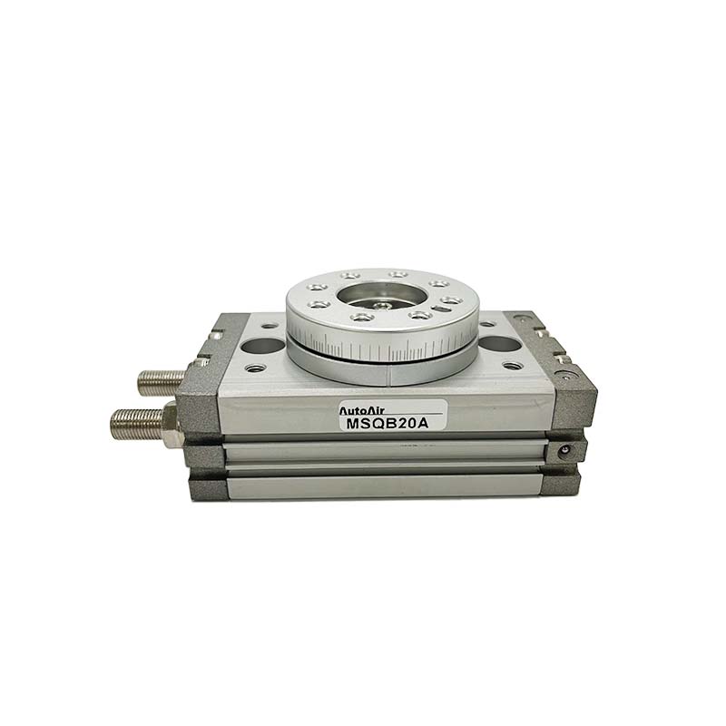
CRQ2 Series: High-torque models with optional hydraulic buffers, suitable for medium-load applications (e.g., valve control, conveyor rotation).
CRA1 Series: Heavy-duty cylinders with large output torque and corrosion-resistant construction, designed for harsh industrial environments (e.g., machining, construction equipment).
Pneumatic rotary cylinders are versatile and find use across nearly every industrial sector that relies on automation. Their ability to deliver precise, fast rotation makes them a go-to solution for the following applications:
Valve & Damper Control: Rotating valves, gates, and dampers in manufacturing, water treatment, and HVAC systems. For example, a 90° rotary cylinder opens or closes a ball valve to regulate fluid or air flow.
Robotic Motion: Actuating joints in small robots or collaborative robots (cobots) for tasks like pick-and-place, assembly, or inspection.
Conveyor Systems: Rotating conveyor sections to redirect products (e.g., sorting packages in a warehouse).
Workpiece Flipping: Turning heavy components (e.g., metal sheets, plastic parts) during machining, painting, or assembly to access multiple sides.
Machining Fixtures: Rotating clamps to secure workpieces in place during drilling, milling, or grinding. The high torque ensures the workpiece remains stable, reducing machining errors.
Assembly Line Locking: Locking components into position during assembly (e.g., securing a car part while bolts are tightened).
Labeling & Capping: Rotating bottles, jars, or containers to align labels or tighten lids. For example, a 180° rotation ensures a label is applied evenly around a bottle.
Carton Folding: Rotating arms to fold carton flaps or seal packages in high-speed packaging lines.
When selecting a pneumatic rotary cylinder for an application, the following parameters must be evaluated to ensure optimal performance and compatibility:
| Parameter | Description | Typical Range | Key Consideration |
|---|
| Working Pressure | The range of compressed air pressure required for operation. | 0.10–0.70 MPa | Ensure the air supply system can deliver pressure within this range; higher pressure increases torque. |
| Proof Pressure | The maximum pressure the cylinder can withstand without permanent damage (for safety). | 1.50 MPa | Critical for applications with pressure spikes (e.g., sudden air flow surges). |
| Ambient Temperature | The temperature range in which the cylinder operates reliably. | 0°C–60°C | For sub-zero environments, use antifreeze additives in the air supply. |
| Rotation Angle Range | The minimum and maximum angle the cylinder can rotate. | 0°–190° (adjustable); 90°/180°/270° (fixed) | Match the angle to the application (e.g., 90° for valve control, 180° for flipping). |
| Output Torque | The rotational force the cylinder can deliver (varies with working pressure). | 5–500 N·m (depending on size/model) | Ensure torque is sufficient to move the load (e.g., heavier workpieces require higher torque). |
| Applicable Fluid Medium | The type of fluid used to drive the cylinder. | Filtered, dry compressed air (ISO 8573-1 Class 4.2.1) | Contaminants (oil, water, dust) can damage seals—use air filters and dryers. |
| Cushion Type | The mechanism for end-of-stroke shock absorption. | Fixed screw or hydraulic | Choose hydraulic buffers for heavy loads or high speeds. |
To maximize the service life and reliability of pneumatic rotary cylinders, follow these best practices:
Clean Internal Components: Before installation, remove any debris (e.g., metal shavings, dust) from the cylinder body, ports, and rotary shaft. Contaminants can cause seal damage or jamming.
Verify Air Supply: Ensure the compressed air is filtered (to remove particles >5 μm) and dry (to prevent water condensation). Use a pressure regulator to set the working pressure within the cylinder’s specified range.
Low-Temperature Environments (<0°C): Add an antifreeze additive (compatible with pneumatic systems) to the air supply to prevent water in the cylinder from freezing and damaging components.
Humid or Corrosive Environments: Use a cylinder with enhanced corrosion resistance (e.g., anodized aluminum alloy) and install a dust cover over the rotary shaft to prevent moisture ingress.
Seal Inspection: Check seals for wear, cracks, or leakage every 6 months. Replace damaged seals immediately to prevent pressure loss.
Lubrication: For cylinders without pre-lubricated components, add a small amount of pneumatic lubricating oil (ISO VG 32) to the air supply monthly to reduce friction.
Sensor Calibration: If using magnetic sensors, recalibrate them annually to ensure accurate position detection.
Autoair, a leading manufacturer of pneumatic components, offers a range of high-performance pneumatic rotary cylinders designed for industrial automation. Key features of Autoair’s models include:
Rack-and-Pinion Structure: Ensures smooth, precise rotation with minimal noise.
Dual-Cylinder Design: Delivers double the output torque compared to single-cylinder models, making it suitable for medium-load applications.
High Machining Accuracy: Achieves angular positioning accuracy of ±0.5°, ideal for precision tasks like robotic assembly.
User-Friendly Installation: Equipped with standardized mounting holes in the worktable center, simplifying integration into existing systems.
Durable Construction: Uses anodized aluminum alloy for corrosion resistance and long service life (up to 1,000,000 cycles).
For detailed specifications, custom solutions, or technical support, contact Autoair’s customer service team.
Pneumatic rotary cylinders are a cornerstone of modern industrial automation—offering a balance of precision, speed, and cost-effectiveness that electric or hydraulic systems often cannot match. By understanding their design, features, and applications, you can select the right cylinder to optimize your automation processes and improve operational efficiency.


